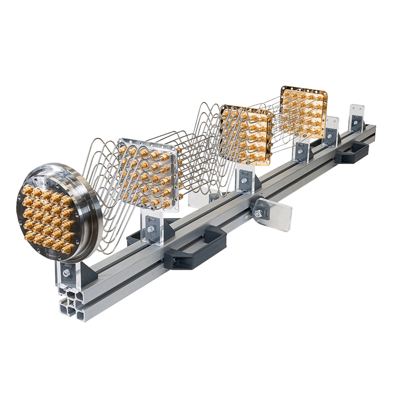
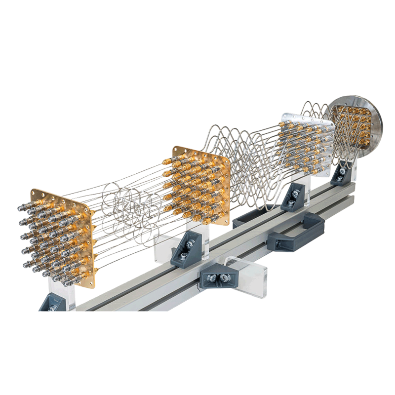
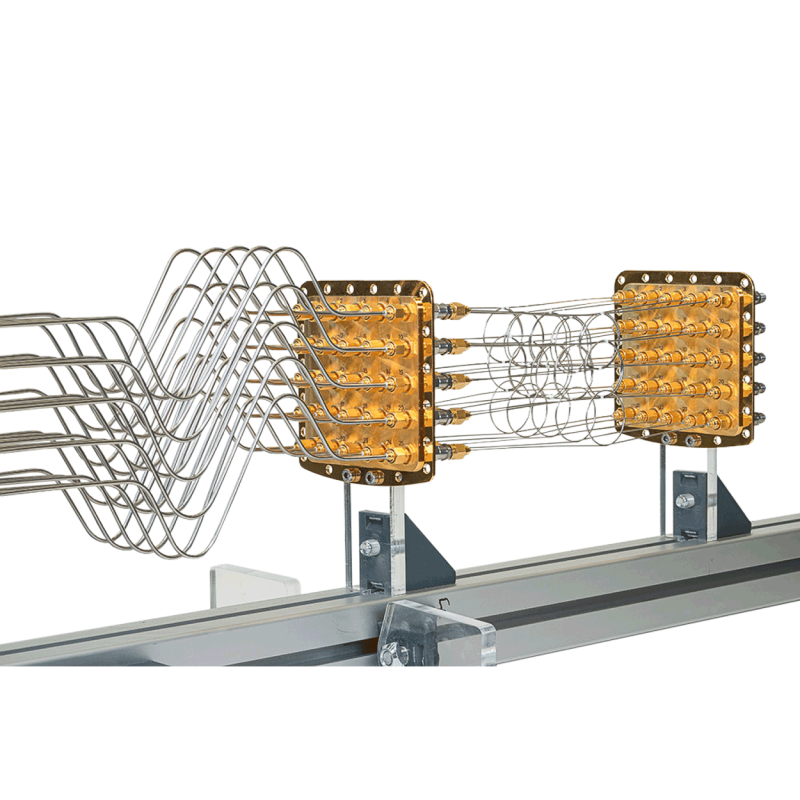
H-gate lines carry bias and microwave signals from room temperature to the mixing chamber. Each run is anchored on the way down so a practical factory build can stay near 10 mK.
Microwave lines
Semi-rigid
Up to 40 GHz · SMA male (18 GHz) or K / 2.92 mm male (40 GHz) · RF installation set
Semi-rigid coax for high-frequency runs. Each stage uses a female-to-female bulkhead. Screw the attenuator onto that bulkhead so the center conductor is heat-sunk as well as the shield. PTFE alone does not thermalize the center pin.
Use 2.19 mm SCuNi only for a few low-loss lines paired with NbTi. In quantity it loads the 4 K stage, and it is not used in high-density RF wiring.
Room temperature to 4 K, SMA 18 GHz
Property
2.19 mm SCuNi-CuNi
0.86 mm SCuNi-CuNi
Impedance
50 Ohm
50 Ohm
Dielectric PTFE
1.67 mm
0.66 mm
Center conductor
CuNi, Ag-plated, 0.51 mm
CuNi, Ag-plated, 0.20 mm
Outer conductor
CuNi, 2.19 mm
CuNi, 0.86 mm
Attenuation, 300 K
1.2 dB/m @ 1 GHz · 3.8 dB/m @ 10 GHz
3.0 dB/m @ 1 GHz · 9.5 dB/m @ 10 GHz
Attenuation, 4 K
0.6 dB/m @ 1 GHz · 1.8 dB/m @ 10 GHz
1.5 dB/m @ 1 GHz · 4.6 dB/m @ 10 GHz
Thermal conductivity, 4 K
2.2×10⁻⁴ W·cm/K
7.1×10⁻⁵ W·cm/K
4 K to mixing chamber, SMA 18 GHz
K / 2.92 mm connectors raise the rating of a high-frequency build to 40 GHz. The cable figures below are the SMA 18 GHz constructions.
Property
0.86 mm SCuNi-CuNi
0.86 mm NbTi-NbTi
Impedance
50 Ohm
50 Ohm
Dielectric PTFE
0.66 mm
0.66 mm
Center conductor
CuNi, Ag-plated, 0.20 mm
NbTi, 0.20 mm
Outer conductor
CuNi, 0.86 mm
NbTi, ~0.86 mm
Attenuation, 300 K
3.0 dB/m @ 1 GHz · 9.5 dB/m @ 10 GHz
9.0 dB/m @ 1 GHz · 30.5 dB/m @ 10 GHz
Attenuation, 4 K
1.5 dB/m @ 1 GHz · 4.6 dB/m @ 10 GHz
< 0.5 dB from DC to 20 GHz
Thermal conductivity, 4 K
7.1×10⁻⁵ W·cm/K
4.63×10⁻⁶ W·cm/K
Low-noise readout
Grapho flexible
Up to a few GHz · SMA male · RF installation set
Flexible SCuNi with a graphite-coated dielectric and an FEP jacket. The jacket tightens on cooldown so the conductors move less. That cuts triboelectric noise from a contracting PTFE dielectric. Useful when a semi-rigid line would be too microphonic, up to a few gigahertz.
Flexible Grapho SCuNi-CuNi
Property
Published build
Impedance
50 Ohm
Dielectric
PTFE, 0.66 mm, graphite-coated
Center conductor
CuNi, Ag-plated, 0.20 mm
Outer conductor
CuNi braid, 90% shielding
Jacket
FEP over the outer conductor
Attenuation, 300 K
5.4 dB/m @ 1 GHz
Attenuation, 4 K
4.3 dB/m @ 1 GHz
Filtered DC
Thermocoax
DC and low frequency · SMA at the warm box and at the cold breakout · DC installation set
Sets of six lossy Thermocoax lines from room temperature to the mixing chamber. High frequencies are filtered, leaving a coaxial geometry for DC and low-frequency bias. Lines are 3 m, wound on gold-plated copper bobbins at every stage. A breakout at 4 K is optional.
Room-temperature resistance and capacitance
Property
RT to MXC
RT to 4 K
4 K to MXC
Length
3 m ± 5%
1.9 m ± 5%
1.5 m ± 5%
Diameter
0.5 mm ± 5%
0.5 mm ± 5%
0.5 mm ± 5%
Resistance
155 Ω ± 5%
100 Ω ± 5%
80 Ω ± 5%
Capacitance
562 pF ± 5%
356 pF ± 5%
281 pF ± 5%
DC to 5 GHz
Continuous CuNi
Up to 5 GHz · SMA at the warm breakout and at the cold terminal · DC installation set
Continuous 0.86 mm CuNi-CuNi lines in sets of six, for DC and low frequency in a coaxial geometry. Less resistive than Thermocoax, with a higher cutoff, but the tight loops inside the bobbins hold the useful band to about 5 GHz. Extra breakouts can be added at the stages you choose.
How this line differs from Thermocoax
Property
Continuous CuNi
Thermocoax
Useful band
Up to 5 GHz
DC and low frequency
Construction
0.86 mm continuous CuNi-CuNi
0.5 mm Thermocoax, sets of six
Resistance
Lower than Thermocoax
155 Ω over 3 m, room temperature
Anchor
Gold-plated copper bobbins
Gold-plated copper bobbins
Warm interface
KF40 breakout, up to 24 SMA lines
KF40 box, 24 lines, or 48 with two boxes
Installation
DC installation set
DC installation set
06
Installation sets
DC installation set
Gold-plated copper bobbins sit on the DC flanges. The set includes a hermetic connector box at room temperature, one aluminium flange, and four copper flanges for 50 K, 4 K, the still, the cold plate, and the mixing chamber. Thermocoax and continuous CuNi use the KF40 port, which takes 3 or 4 feedthroughs.
RF installation set
Semi-rigid and Grapho lines thermalize on female-to-female bulkheads at each stage. The set includes the warm hermetic feedthrough and is sold without cables or attenuators. Screw attenuators onto the bulkheads so the center conductor is heat-sunk with the shield.
KF251 SMA (18 GHz) or K 2.92 mm (40 GHz) feedthrough
KF404, 6, or 7 feedthroughs
ISO-K638, 12, 16, 20, or 21 feedthroughs
ISO-100 side-loader25 or 32 feedthroughs
07
Technical requirements
Thermocoax and continuous CuNi go into a KF40 port with a DC installation set. Grapho and semi-rigid lines need an RF installation set.
 H-GATE